Click all framed photos to enlarge.
 |
 |

|
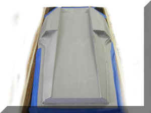
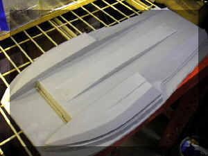
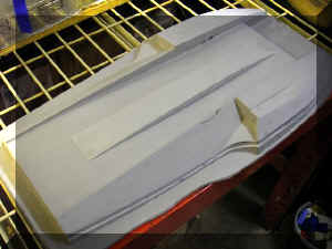
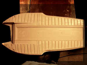
| Hull mold. |
Smooth underside for installing air dams or
tunnels to the mold later. |
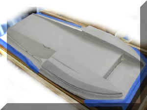
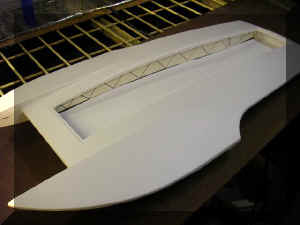
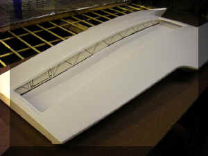
Deck formed. Test fit of outer hull to outer
deck. |
 |
 |
 |
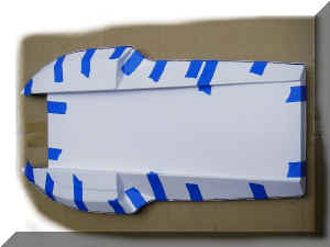
| Hull formed. |
Black urethane sealant used to bond the hull. |
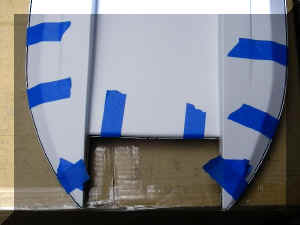
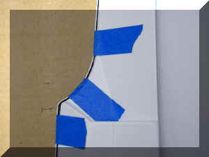
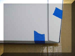
Seam at rear of sponsons. |
 |
 |
 |
| Seam at transom. |
Starboard Stringer (Concept) Production
stringers may be aluminum 1/8" x 3/32" member bar joists with
the same geometry as the black lines on this PVC prototype. |
Port Stringer (Concept) Pre-cut and
Pre-drilled micro servo mount on one side. Receiver opening on other side.
Space between stringers
will be approximately 4-1/16 inches. |
 |
 |
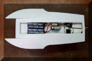 |
| Locating gear for Liner design. N-2
Sport Hydro. Was able to obtain a proper CG. |
Really gets your imagination going! Not
practical to build this one as the hull has no reinforcing liner
installed. Looks pretty but its just not ready yet. |
Was able to get the CG in Limited Sport Hydro
as well. For those who want a 1/4" right offset drive, the ply motor
mount base can be easily modified to shift the motor without modifying the
hull. |
 |
 |
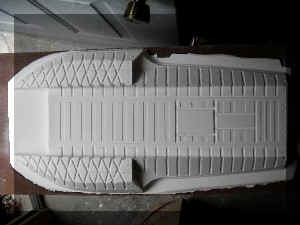 |
| Tunnel set in place on the hull mold. This last
detail makes it faithful to the original design and build. |
However, it can be removed to
experiment with other designs and configurations.
(Later, prototype testing and designer
consulting determined that the tunnel could be omitted without affecting
performance.) |
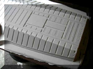
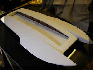
Rough hull liner mold. Still have to mill
the bed for the graphite bow- cross member. |
 |
 |
 |
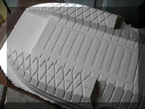
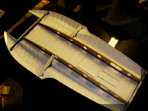
| Trays for motor mount & flex/straight
drive hull penetration. |
Truss mounting grooves in the hull
floor. |
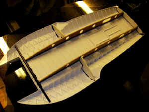
Deck Reinforcement mold in-progress.
Double grooves will secure the rear sponson side bulkheads. |
 |
 |
 |
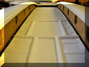
| Note the necessary internal structure is
minimal due to the reinforcing liners to the hull and deck. |
First look at the prototype stringers. They butt
against a large carbon-fiber spar at the bow, a PVC transom reinforcement at the
stern, and PVC sponson baffles. |
First Prototype Completed. Doug is
installing equipment. |
 |
 |
 |
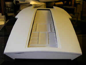
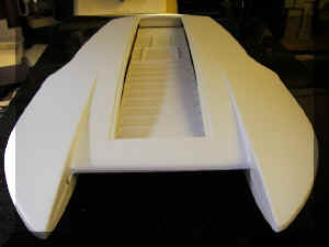
| No hatch cover yet. Need motor-clearance
measurements from Doug to design it. |
Nice lines. |
Rock-Solid deck. |
 |
 |
 |
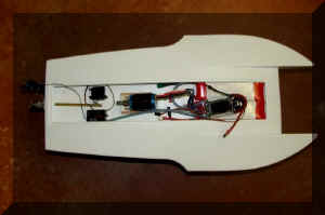
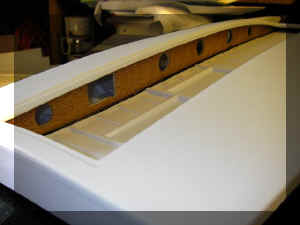
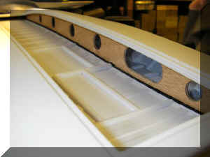
| Port stringer has mount for mini-servo. |
Starboard stringer has hole for
receiver. |
Maiden voyage of first prototype to
confirm a working setup. Unsharpened and unpainted hull. No tunnel. LSH
setup. 1 MB Video. |
 |
 |
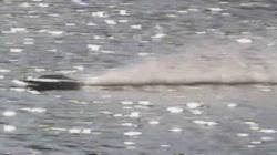 |
| Going in circles. 1.3 MB Video. Recommend
you sharpen & paint before testing. In the water, unpainted styrene
drags more than painted styrene. |
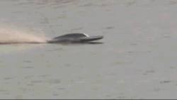
1/6 mile oval at 33 mph. 3.5 MB Video.
Amp-Draw of the motor tests less with a painted hull. |
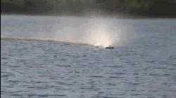
Oval with hull tunnel attached. 3.6 MB
Video. |
 |
 |
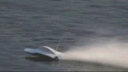 |
| Oval without tunnel attached. 1.7 MB
Video. |
8XL Brushless Setup. 1.7 MB Video. Not a
P-Sport boat. Just playing... |
8XL at 51 mph. 1.6 MB Video. |
| |
|
|
|

With our revolutionary Collision-Damage-Resistant
Vac-U-SeamTM Technology.
A new boat needs a new Logo. Meet our
Spokes-Pickle. |
| |
|
|
| Using hand-cut wood
and PVC reinforcements, several prototypes were produced for testing.
Due to their popularity, several more were required. |
| |
|
|
| |
|
|
| The hatch cover design is
temporary. It was the last-minute effort to cover the large hole in the
top of the deck in time for the Chattanooga Invitational. |
|
|
|
|
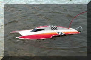
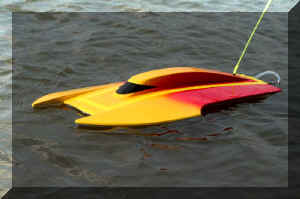
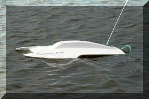
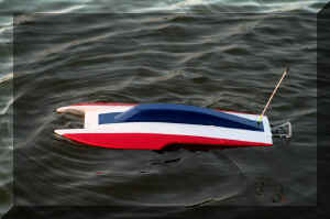
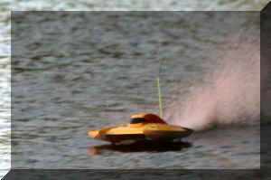
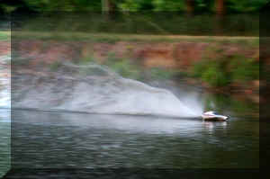
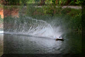
Prototype racing in Chattanooga 2007. |
|
 |
 |
 |
| Chris's |
Doug's |
Rick's |
 |
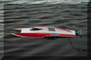 |
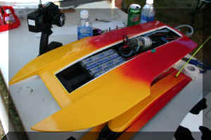 |
| John's |
Chris's w/ lighter LiPoly Batteries to
compare water-line. |
NiMh batteries close to motor. |
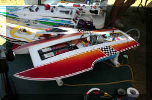 |
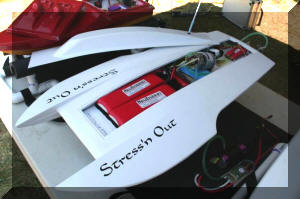 |
 |
| LiPoly batteries farther forward |
Same here. |
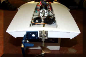
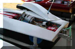
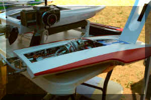
Typical LSH Hardware Setup. Motor and
bracket are removable from the ply base plate. |
 |
 |
 |
| Motor looks high but is on a low-profile
mount at 15 degrees down. |
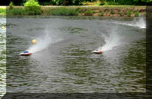
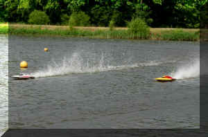
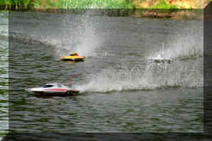
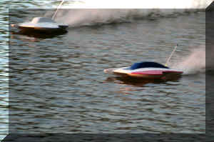
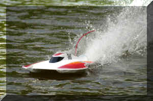
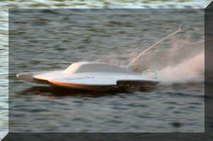
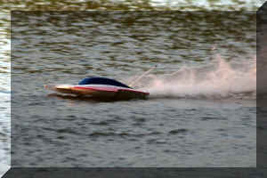
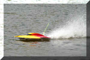
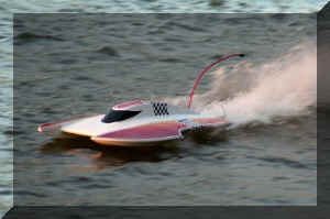
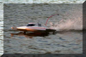
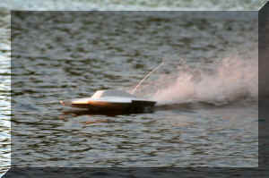
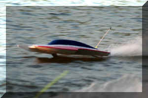
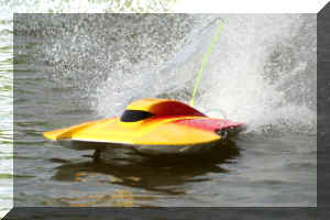
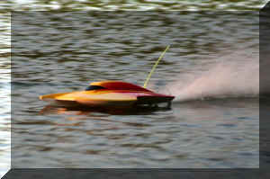
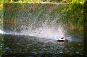
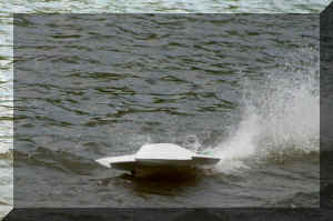
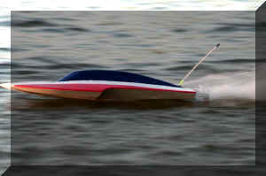
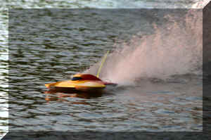
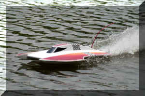
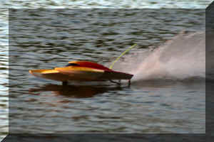
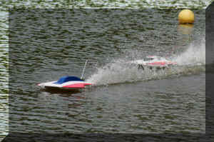
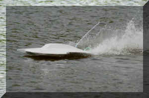
A few friendly racing pics |
to show the ride of the kit. |
 |
 |
 |
|
|
|
 |
 |
 |
|
|
|
 |
 |
 |
|
|
|
 |
 |
 |
|
|
|
 |
 |
 |
|
|
|
 |
 |
 |
|
|
|
 |
 |
 |
|
|
|
 |
 |
 |
|
|
|
|
|
|
| |
|
|
|
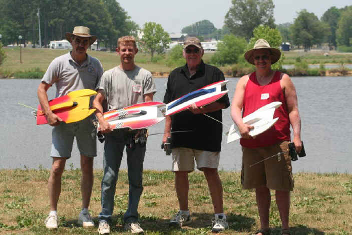
June 17, 2007 Chattanooga Invitational. Vac-U-Pickle hulls
placed 1st, 2nd, & 3rd in first race. Placed 1st & 2nd in the second
race.
|
| |
|
|
| Final drawings were
transferred to CAD to produce laser-cut ribs, transom reinforcement, and
sponson baffles from hot-pressed mahagony plywood. A product that can be
boiled for 3 hours and still pass a shear-test for strength. Pulltruded
carbon-fiber rod was the best support for the front of the sponsons. |
| |
|
|
 |
 |
 |
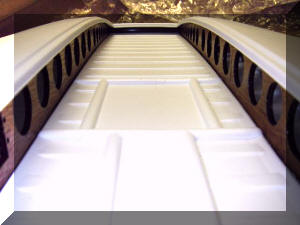
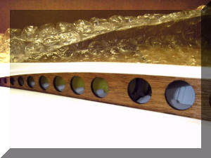
| View toward bow and the Carbon Fiber Sponson Brace. |
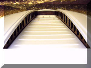
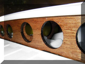
View toward the stern and its 3/16" thick hot-pressed
mahogany reinforcement. |
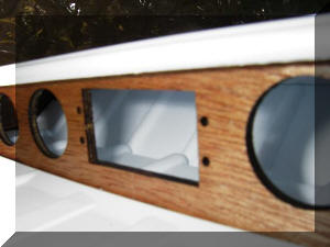
Pre-drilled servo box in port rib. |
 |
 |
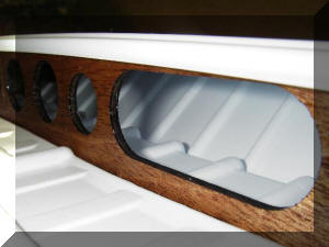 |
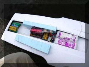
| Flotation visible inside the sponson. |
Rear sponson Reinforcement Baffle visible through the
starboard rib. |
Radio Receiver access opening in the starboard rib.
|
 |
 |
 |
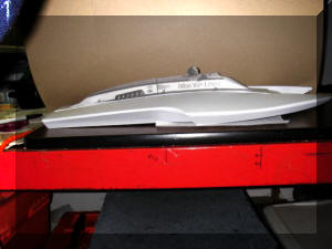
| Photo of the real Atlas taped to hull for review. |
Now, had to get to work to make one. |
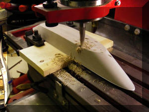
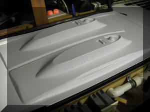
Test-Form over the "Atlas" cowl mold. |
 |
 |
 |
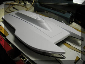
| Good fit. Additional designs will follow later. |
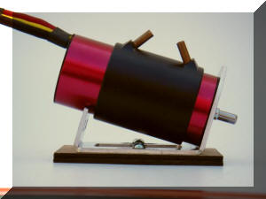
A perfect motor mount was needed. This was the
result. |
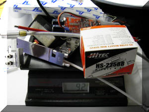
Took all of the building hardware and weighed it for
the float test. |
 |
 |
 |
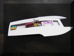
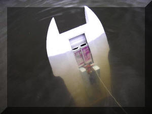
| In the water with a brushless XL 540 motor, 2 nicad
packs, and AA cells equal to the hardware and receiver pack's weight, as
heavy as it could be built with a total load of 49.1 ounces (Not
including the weight of the hull). |
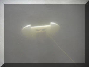
Removing all air trapped in the sponsons, it slowly
sunk. |
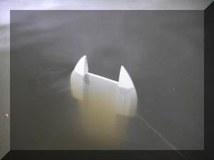
Leaving trapped air in the sponsons, it floated, but
not enough. |
 |
 |
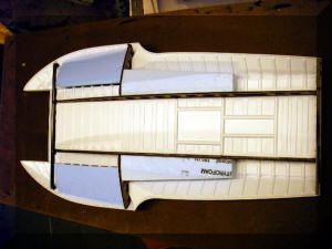 |
| Added two strips of foam to the after-planes. |
Successful test. Plenty of flotation in case the
worst happens. |
Final flotation configuration. |
| |
|
|
| Production Begins! |


 TM
TM